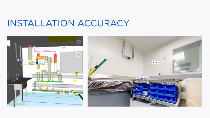
During a tank-room renovation in an existing building, ENG’s mechanical team transferred 2D design drawings into a preliminary 3D model. While BIM detailers and the foreman were collaborating through SmartReport, a digital twin platform, they discovered a 5-inch discrepancy between the model and the actual distance between a wall and a window.
That simple breakthrough (enabled by advanced technology and solutions for construction) resulted in preventing rework and proving how digital collaboration improves installation accuracy.
With new automation tools and connected workflows, teams can now accelerate the shift from design data to fabrication (LOD 400) models that drive real-world performance.
So how does that process actually work? Let’s start with the basics.
What’s the Difference Between a Design Model and a Fabrication Model?
In every BIM project, the design model (LOD 200) serves only as a reference, showing intent but not the full constructible details. On the other hand, the coordination model brings different trades together, helping mechanical, electrical, and plumbing systems align and detect clashes. However, it’s the fabrication model (LOD 400) that sets the standard for accuracy.
For mechanical contractors, this distinction matters. The higher the Level of Development (LOD), the more precise and buildable the information becomes, turning design data into real-world assemblies ready for the shop and the field.
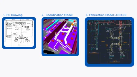
The Simplified BIM Workflow
1. IFC Drawings (LOD 200) → The design reference, used to share system layouts and intent.
2. Coordination Model → Aligns trades and resolves routing or clash issues.
3. Fabrication Model (LOD 400) → The final buildable version with exact pipe lengths, hangers, sleeves, and spools.
| Model Type | Purpose | Detail Level |
|---|---|---|
| Design Model (LOD 200) | Shows design intent and general system layout | Basic geometry and schematic information |
| Coordination Model | Aligns trades and resolves clashes | More realistic routing and space allocation |
| Fabrication Model (LOD 400) | Drives construction and prefabrication | Exact dimensions, part data, and constructible accuracy |
What Causes Delays Between Design and Fabrication in BIM Projects?
Even with the best BIM intentions, many mechanical & plumbing projects still stumble between design, coordination, and fabrication. Yet, delays’ root causes between design and fabrication in BIM are common and completely preventable.
Common workflow challenges:
- Inconsistent inputs. Design models often arrive incomplete or in the wrong format, forcing remodels before coordination even begins.
- Complex setup. Establishing templates, parameters, and part databases consumes days that should be spent on modeling.
- Manual modeling. Repetitive routing and spacing drain productivity and invite human error.
- Slow spoiling: Manual spooling delays production and pushes back installation schedules.
Each pain point reveals the same truth: inefficiencies grow when teams, tools, and data are disconnected.
How Can Contractors Reduce Time Using BIM Automation Tools?
Success depends on smarter connections between the office and the field, design and fabrication, and between humans and automation. In practice, that connection happens through three layers of technology that work together to streamline the design-to-fabrication process.
1. Core MEP Tools: The Industry Foundation
Every efficient workflow starts with standardized content and data management.
MEP professionals rely on Fabrication CADmep, MEP Content Editor, and other native Revit-based tools to manage parts, materials, and templates. These platforms ensure that every component follows the same data standards, reducing rework and maintaining code compliance across projects.
2. Specialized Add-Ins: Automation for Constructible Models
Beyond the core tools, mechanical contractors increasingly use ready-to-deploy BIM add-ins to eliminate repetitive work and accelerate accuracy.
Applications such as Stratus, BIMPro, and Evolve MEP handle tasks like spooling, hanger creation, and fabrication coordination, turning what once took days into minutes.
These tools extend the capabilities of Revit and Navisworks.
3. ENG Custom Add-Ins: Internal Innovation at Scale
Where most firms stop off-the-shelf automation, ENG’s innovation team has built its own suite of custom tools. The Mechanical and Plumbing team created more than 59 proprietary add-ins specifically for their workflows.
Among the most impactful are:
- Design2Fab – Converts Revit design piping into fabrication parts automatically.
- MEP Spacing – Applies code-compliant separations between pipes with a single command.
- FabRouting – Speeds up routing, allowing multiple pipes to be modeled in seconds.
- Coordinate (Niagara-to-Revit) – Synchronizes clash adjustments between Navisworks and Revit.
These automations are embedded across both AEO (Architectural Engineering Operations) and GEO (Global Engineering Operations) teams, driving consistency and measurable efficiency.
Conclusion: Turning Design Data into Field-Ready Results
Automation is transforming how mechanical contractors deliver precision in every phase of construction. When connecting design intent with fabrication reality, ENG enables teams to convert early-stage BIM models into fabrication-ready (LOD 400) driving accuracy, consistency, and speed.
If you are ready to see how automation can redefine your BIM-to-fabrication workflow watch ENG’s on-demand webinar “From Design to Fabrication: Streamlining MEP Models with New Automation Tools.”
Or contact ENG to explore scalable solutions for your next project.